Failed Road Embankment and the Probable
Causes
This almost 20m high new paved road
embankment at a hilly terrain in Bintulu Division failed completely after heavy
rain. Why?
The road embankment is crossing a slanting, narrow and deep valley, with hill less than 5m away.
There are five main factors which affect the road
embankments:
(a) the design, the slope
provided, the foundation and the earth materials used for the filled embankment,
(b) the method of
construction of the filled embankment,
(c) the rain and effective
drainage,
(d)
the traffic
(e)
the breakage of water
supply pipe
(f)
the maintenance.
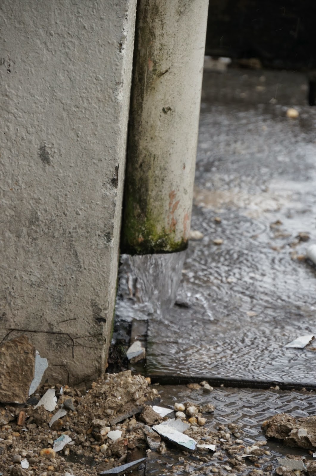
From
the photograph, it can be seen that it was a complete collapse of the filled
embankment, some soil slurry was seen flowing from the right side down the
slope. There seemed to be a large depression on the right hand side of the road
which was part of valley, and probably formed a pond after heavy rain. No
concrete drain was seen and earth drain was presumed. No much vegetation was
seen on the right hand side indicating new construction. Turfing or vegetation
had not covered the bare surface completely. Water pipe was not seen on the embankment.
The
embankment was stable for a while after construction when there was no much
rain. It was the rainfall and poor drainage which resulted water infiltrated
into the fill embankment and weakened the soil.
It was also the accumulated pond water which continuously supplying
water into the embankment soil until the soils were saturated with a lot of
free water.
Just
soak a compacted soil sample in the water, you will see the immense change of
moisture content, CBR and hence the strength. If you vibrate it, the whole
sample would liquefy and becomes slurry. Heavy lorries and machineries cause
vibration.
As
there was no water pipe, it was not the water leakage that infiltrated into the
embankment. In fact many filled embankments failed because the water pipe
broke. This often occurred at the junction of the excavated road and filled
embankment which settled due to poor foundation, compaction and erosion.
Thus,
from the sudden failure of the whole embankment, it looks more like slope
stability/foundation sliding failure, which means average strength of the embankment materials has
gone below the design requirements. Water seepage changed the properties of the
earth-fill materials.
To prevent such problem, design-wise,
always provide efficient drainage for this kind of high fill embankment. Any depression shall be filled and levelled at
the road side, must indicate on the Plan. No water pond shall be allowed to form. If the soil materials
are very permeable and erodible, concrete drains have to be provided to prevent
water seepage into the filled embankment. It is an advantage to have a few
layers of coarse grained materials in the embankment to allow water to drain
through to the other side efficiently, but shall not in a way allowing erosion
of these layers. The bottom layers and toe of the slope are preferably large
and small crusher stones mixed with coarse sand, to allow for such drainage.
On
the construction, the valley bottom in the hilly area is often weathered to
reach rocks, but sometimes, there are some shallow colluvials soils, which can
be easily excavated and replaced with rocky materials. Higher valley sides need
to excavate 0.3-0.5 m soil and replaced with compacted soil to ensure proper
anchoring and no weak contact layer. This step will form firm foundation and prevent sliding along the slanting valley.
The
choice of fill materials from the borrow pits and degree of compaction will
affect the performance of the embankment. Always investigate and test the
materials before use. For road project, there is always a soil laboratory
specified for doing such tests. If the materials are too silty, compaction is
difficult, especially during raining. Clay also cannot be compacted during
raining. Just look at the Compaction Curve of the Compaction Test and see how sensitive is the moisture content on
the field density. It is difficult to achieve 90-95% optimum density due to
high water content. In fact, no work shall be done during raining, unless you
use gravelly or sandy materials. Gravelly materials are hard to find generally
though. The excavation of borrow pits often begin at he surface which is generally firm to hard residual soils followed by highly weathered rocks. The surface soils are often used for the foundation layers of the embankments while the rocky soils are used on the top. Planning shall be in such a way that the rocky materials are used for the bottom layers.
Sarawak
is in the tropical zone, hence rainfall is a common occurrence throughout the
year. The dry season may be during May-August, but can construction wait until
that period?
Another
problem with the local Contractors is they like to dump-fill into the valley to
build up the embankment without compaction, sometimes not even make foundation
clearing and preparation. This is the easiest and fastest way to build up high
embankment, especially when the Supervisors are not around. Just bore down the embankment
and do SPT tests, you can detect which layers are compacted and which are not. Well
compacted soil has SPTs more than 5 (depending on the materials used, compacted
sands have SPT more than 10), those less
than 3 were not likely compacted although the seepage of water would also lower
the SPTs. Built-up embankments do not fail easily if there is no much water
seepage or erosion, but uneven settlements on the road pavement will occur.
Maintenance includes inspection, clearing, repair of the drains and turfing of any bare ground, which inhibit water to infiltrate into the filled embankment. The Authority often has insufficient fund allocated for inspection and maintenance.


b.jpg)