Sunday 13 December 2015

Excavating Rocks - Rip-able or Un-rip-able

Road engineers often have to face the challenge on deciding whether the roads they designed at hilly/ mountainous areas, can be excavated cheaply so as to achieve safe and gentle road gradient for the road users. Of course, the engineers can design to the safest gradient theoretically with the latest high capacity excavating equipments and blasting, but the cost can be exorbitant which renders the project not feasible. This is particular true for under developed countries where budgets are limited. Modern living requires shortest distance and safest road gradient between the two points. In the mountain regions, mountains have to be excavated and valleys filled up or bridges built to satisfy such needs. But deep excavation often encounters hard rocks and rock excavation is expensive. It generally costs about US$2-4 to excavate and filling of soils, but will cost more than US$10-20 to excavate rocks, depending on the remoteness of the project sites. A balance has to be made between safety, comforts, distance and costs. The knowledge of the machineries available locally and rip-ability of local rocks become important so that the designers can decide which lowest and most economical excavated levels the local builders can achieve.


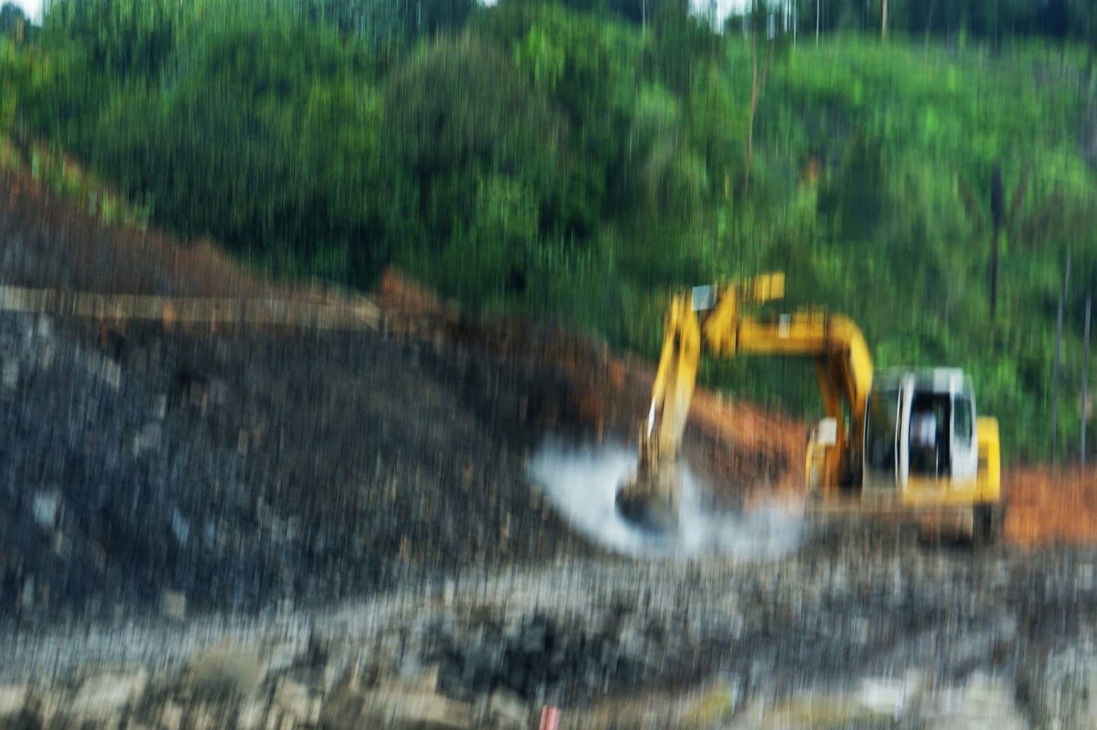
These photos show the 20 ton capacity excavator being used to rip the rock. Obviously, this machinery is not suitable for ripping as capacity is low and the energy splits between the many teeth of the dipper. But as the rock is Shale, a soft rock, he may be able to rip slowly. But much energy is lost through friction and heat. Perhaps, this Contractor feels freer and economical to use his own available machine then to rent a D8 bulldozer with the ripper from others.

On the local scene, D8L with the ripper, having 335 horse power and weighing 25 tons, is the standard machinery specified to decide whether the rock is to be paid “rock rate”. If it is able to be ripped by this machine, then it is considered “earth or non-rock”. If not, it is paid “rock rate”. But in view of the high difference in cost, the Contractor obviously wants to claim rock rate while the client wishes to pay only non-rock rate. Thus Contractor may use an under-powered D8L to prove his point or even ask the drivers to cheat on the use of gears or operations so as to show the rock is not rip-able. Sometimes, road projects were abandoned because of this controversy, especially if the engineers provide low quantities of un-rip-able rock in the Contract. Of course, the design engineers can re-design the gradients to minimise rock excavation, but the safety of the roads may be compromised beside delay of projects. I remembered one road with a road gradient of 25% in some stretch to a hill resort, became accident prone stretch within one month of the opening. The cost and safety of the road is closely related.

But how to determine whether the rock is rip-able or not? Engineers nowadays easily acquire road design software to come out with beautiful lines, graphs, figures to even two decimals, cross-sections and quantities. But to estimate the non-rip-able rock from this standard software is beyond its capabilities. The engineers have to decide which level is the cut-off point as even 10m away may be different.

The knowledge of geology is the first pre-requisite. It is fortunate that the earlier geologists had come out with a Geological Map of Sarawak, mapping all the different features, geological history and types of rocks of Sarawak at different regions. These geologists of Sarawak Geological Department were great enthusiasts, scientists and explorers, who despite the inaccessible and difficult tropical terrains, ventured to the ground, studied diligently under the hot sun for years during the last century and came out with the geological reports and Maps, which had benefited the geologists/geotechnical engineers today, including me. I saluted them. The fourth edition dated 1986 could be purchased from the Sarawak Geological Department and I often referred to this Map.

Soil investigation is the next important step. Although geological map is a helpful preliminary investigation, detailed soil investigation will confirm the actual nature of the rocks beneath the proposed road. After all, earlier Geologists used generally visual observations of exposed outcrops, features, plus limited borehole drilling to come out the geological map. Some local variations or intrusions of rocks may happen during the tumultuous age of mountain buildings. Types of rocks will straight away 
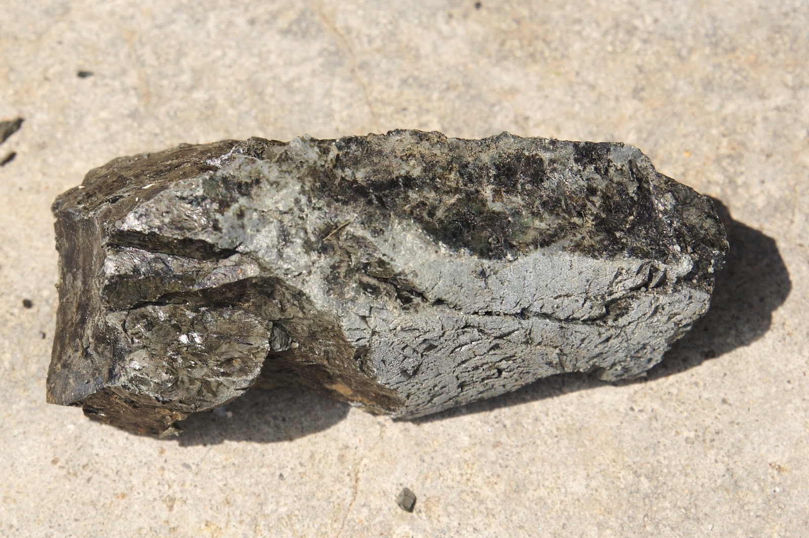
determine whether the rocks are rip-able or not. Igneous rocks, such as Granite, Andesite, Gabbro, Basalt, Microtonalite, etc are generally difficult to rip, unless they are thinly laminated. Sedimentary rocks such as Shale, Siltstone, Mudstone, etc are generally easier to rip, but not the Limestone which is strongly bonded by chemical and can reach a strength of exceeding 30N/sq.mm unconfined strengths. As of metamorphosed rocks, Quartzite, Schist’s, Gneisses and Slates can be difficult to rip depending on the lamination, mica content and degree of weathering. Drilling boreholes can extract the rock cores beneath the ground for which the Geologists and the Geotechnical Engineers can study the rock samples. Together with Total Recovery Ratio (TCR) and Rock Recovery Designation (RQD), some feelings on the rock rip-ability can be made but not absolute. Drilling procedures, such as vibrations and water entries may produce totally shattered samples, which appear easily rip-able.

Seismic survey is sometimes deployed for larger road projects. Caterpillar (1983) and Smith(1986) had co-related Rip-able Charts with their research on seismic survey, and are helpful in determining the rip-ability of rocks. Seismic velocity travels 0.3km/s in loose unsaturated soils, but reaches 6km/s in hard rocks. Generally, velocity of 2.0km/s is rip-able while >2.5km/s is unlikely. In between, it is the grey area.

The most popular available excavating machineries used for road construction in Sarawak are Caterpillar D6 bull dozers and 20 tons excavators, mainly at lowlands and small hill areas. But D8 dozers are only owned by some big construction companies. D8L is probably the most common type which is specified in the local road specification. D8 Dozer had evolved from 132 horse powers (hp) in 1932 to 335hp D8L in 1982 and 310 hp D8T in 2004. Power is the most important factor to decide whether the rock is rip-able.
Dozer had since developed into even more powerful machineries, D9, D10 and even D11. These machineries are used to excavate non-rip-able rocks. Although blasting and hydraulically mounted breakers/chisels are another commonly deployed methods used to excavate hard rocks, but blasting requires a lot of safety procedures and relevant approvals which quite often cause delays. Chiselling is too slow for large quantities of rocks. Blasting is often prohibited near dam sites and other sensitive Equipments installations. Therefore, D9 and D10 dozers become the only options to excavate un-rip-able rocks in many areas. These machineries were often used by the large and rich timber corporations in the interior mountainous areas to build roads to transport their logs. With the dwindling of the forests, these timber companies had switched to construct highways which could deploy such machineries. In 1955, D9 had 286hp but by 2004, D9T had reached 410hp. But the most powerful D9 was 1980 D9L with 460hp.  Komatsu D275A probably posed a strong competitor to D9. In 1987, Caterpillar introduced 700hp D10 and 520hp D10N, weighing 82-86 tons. Komatsu came out with D455A with 620hp and weighed 76 tons. By 1986, Caterpillar produced 770hp D11N weighing about 102 tons with ripper, and by 2008 developed 850hp, 120 tons D11T. Komatsu responded with 1150hp D575A weighing 168tons. Such huge machines would be damaging to move on the local roads. I had seen D9 and D10 in the timber concessions, but I am not sure whether there is any D11 bull dozer in Sarawak.

Availability of large excavation machineries does not mean cheaper rock excavation cost. These machineries are expensive to procure, and probably not only the manufacturers monopolise the market, the owners also monopolise the local construction market. When budgets are limited or the country is poor, Engineers have to propose a design of steeper gradients with less excavation, slower speeds and longer routes. Road users have to be more careful, drive slowly and ensure that their cars are maintained road-worthy.
When you are poor, you cannot expect too much.


Tuesday 8 December 2015

Properties of Microtonalite Rock

The following tests had been done on one batch of this rock with the following average results:
(a) Specific gravity    =  2.58
(b) Aggregate Value  =  18%
(c) Impact Value        =  16%
(d) Water Absorption =  1.55
These results indicate that this rock can be used for structural concrete and pavement concrete. The specific gravity is slightly lower than other igneous rocks, Granite, Gabbro, Andesite and Basalt which have SG of about 2.79.


Microtonalite Rock 

My drilling friend lends me some more of these rock samples, they are just simply beautiful, very light grey and slightly greenish.
Recently, they seemed to strike this type of rock often in the Kuching/Serian area.


Thursday 5 November 2015

Calcareous Microtonalite

It is a beautiful white rock sample taken from 12m below ground level around Serian Volcanic area. It has pale shade of green across the section which indicates the presence of  chlorite. Indeed, it reacts mildly with hydrochloric acid. If it is limestone, it would react violently with the acid. It is solid and heavy and is an igneous rock.


Wednesday 4 November 2015

Light Grey Sandstone

This core sample has less brown stain compared to that shown earlier and exposes the cleaner light grey colour.  The grains are coarse and clearly seen.
It was extracted 4m below the ground level, a relatively shallow rock at Serian District.


Tuesday 27 October 2015

Dark Grey Mudstone

Dark Grey Mudstone is one of the most common Sedimentary rocks in Sarawak, especially at the Central and Northern Sarawak. It can be massive but quite often in alternate layers with Sandstone, Siltstone and Shale. This Sample was obtained, however, from the Western Sarawak.


Friday 23 October 2015

Light Grey Conglomerate

You would think that this is a poor concrete core.
No, it was extracted 11m depth below the ground, not far from the junction of Pan Borneo trunk road to Simunjan.

It is not a common sedimentary rock, characterised by cemented gravels and cobbles. The gravels appear to be only slightly rounded, indicating that it did not roll down the stream long enough before it got buried and cemented.

If the fragments are finer, angular and irregular, then the rock is called Breccia.


Wednesday 21 October 2015

Light Brown and Grey Sandstones

Sandstone rocks are sedimentary rocks commonly found beneath Sarawak ground, from Kuching to Miri.

This light brown Sandstone core is extracted from about 23m depth.


This light grey Sandstone core fractured to halves, was extracted from about 12m depth.


Monday 19 October 2015

Brownish Orange Mudstone

The rock sample looks more appealing with bright multi-colours. It is not often encountered with this colour for the fine grained sedimentary rock.


Another Sample of Andesite

Although this grey and light green volcanic rock is highly weathered, it is still very hard and heavy. It was extracted about 10m depth below ground level near Serian county.


Friday 2 October 2015

Andesite at Serian Hill

It was identified by Geological Department that the rock found at the Serian Hill, Andesite. This rock is another most common igneous rock after Granite and Basalt. To identify the rock type, microscope is required to identify the minerals (petragraphy). When cut open, the surface  is very smooth, and the colour is light bluish and grey, fine grained and crystallised.
The name Andesite originated from the South America's Andes and is associated with lava flows or volcanic activities.


Thursday 27 August 2015

Repair of Failed Column

Finally, the repair of failed column is almost completed after three months of construction. 
No rental, no business activity, it was quite a loss besides the repairing cost
But luckily, no body was hurt. Hopefully, it is safe now and can be re-opened soon.


Rock near Long Lama

This rock core was obtained about 20m depth below a hilly site near Long Lama, Northern Sarawak. Geology in Northern Sarawak is much younger compared to the Southern Sarawak.
It is a sedimentary rock, Mudstone. It is moderately strong, but easily fractured along the vertical plane.


Wednesday 19 August 2015

Serian Volcanic Rock

This rock specimen is found near the hill of  the Borneo trunk road five kilometres after the Sadong Bridge towards Sri Aman (65km from Kuching). It is one of the hardest rocks in Sarawak, the Serian Volcanic lava rock, which was formed during the Triassic period (about 200 to 250 millions years ago). It is harder than the granite rock and is difficult to drill through using ordinary boring machine.


Saturday 25 July 2015

Gravels from 45m Depth below Ground Level

These gravels were extracted with great difficulty from a borehole 45m below the ground level at the upper stream of Baram River. How did they come about?
The River of the hilly area was the formerly deeply eroded valley during the ice age when sea level was low. The rise of sea level about 12,000 years ago and warming resulted in plenty of rain, brought down sands, gravels and boulders  to deposit at the upper stream of the submerged valley.
During boring,  clay,silt,sand could be easily washed out using pressured water flow but not the larger gravels. These gravels accumulated below the bottom of the borehole as the drilling got deeper. It needed some skill to get some of them out of the borehole. Sometimes, the drillers used core barrels and some times they used grouting.

But these gravels have serious impact on the Standard Penetration Tests at the test layers, very high blow counts!  So, engineers have to interpret the soil layers containing gravels,with caution. For example, N=50 blows per 300mm does not mean dense sand, it may be just medium dense sand.


Tuesday 21 July 2015


Failed Road Embankment and the Probable Causes


This almost 20m high new paved road embankment at a hilly terrain in Bintulu Division failed completely after heavy rain. Why?

The road embankment is crossing a slanting, narrow and deep valley, with hill less than 5m away.

There are five main factors which affect the road embankments:

(a)   the design, the slope provided, the foundation     and the earth materials used for the filled            embankment,
(b)   the method of construction of the filled                embankment,
(c)   the rain and effective drainage,
(d)   the traffic
(e)    the breakage of water supply pipe
(f)    the maintenance.

From the photograph, it can be seen that it was a complete collapse of the filled embankment, some soil slurry was seen flowing from the right side down the slope. There seemed to be a large depression on the right hand side of the road which was part of valley, and probably formed a pond after heavy rain. No concrete drain was seen and earth drain was     presumed. No much vegetation was seen on the right hand side indicating new construction. Turfing or vegetation had not covered the bare surface     completely. Water pipe was not seen on the             embankment.

The embankment was stable for a while after construction when there was no much rain. It was the rainfall and poor drainage which resulted water infiltrated into the fill embankment and weakened the soil.  It was also the accumulated pond water which continuously supplying water into the embankment soil until the soils were saturated with a lot of free water.
Just soak a compacted soil sample in the water, you will see the immense change of moisture content, CBR and hence the strength. If you vibrate it, the whole sample would liquefy and becomes slurry. Heavy lorries and machineries cause vibration.

As there was no water pipe, it was not the water leakage that infiltrated into the embankment. In fact many filled embankments failed because the water pipe broke. This often occurred at the junction of the excavated road and filled embankment which settled due to poor foundation, compaction and erosion.

Thus, from the sudden failure of the whole embankment, it looks more like slope stability/foundation sliding failure, which means average strength of the embankment materials has gone below the design requirements. Water seepage changed the properties of the earth-fill materials.

To prevent such problem, design-wise, always provide efficient drainage for this kind of high fill embankment.  Any depression shall be filled and levelled at the road side, must indicate on the Plan. No water pond shall be allowed to form. If the soil materials are very permeable and erodible, concrete drains have to be provided to prevent water seepage into the filled embankment. It is an advantage to have a few layers of coarse grained materials in the embankment to allow water to drain through to the other side efficiently, but shall not in a way allowing erosion of these layers. The bottom layers and toe of the slope are preferably large and small crusher stones mixed with coarse sand, to allow for such drainage.

On the construction, the valley bottom in the hilly area is often weathered to reach rocks, but sometimes, there are some shallow colluvials soils, which can be easily excavated and replaced with rocky materials. Higher valley sides need to excavate 0.3-0.5 m soil and replaced with compacted soil to ensure proper anchoring and no weak contact layer. This step will form firm foundation and prevent sliding along the slanting valley. 

The choice of fill materials from the borrow pits and degree of compaction will affect the performance of the embankment. Always investigate and test the materials before use. For road project, there is always a soil laboratory specified for doing such tests. If the materials are too silty, compaction is difficult, especially during raining. Clay also cannot be compacted during raining. Just look at the Compaction Curve of the Compaction Test  and see how sensitive is the moisture content on the field density. It is difficult to achieve 90-95% optimum density due to high water content. In fact, no work shall be done during raining, unless you use gravelly or sandy materials. Gravelly materials are hard to find generally though. The excavation of borrow pits often begin at he surface which is generally firm to hard residual soils followed by highly weathered rocks. The surface soils are often used for the foundation layers of the embankments while the rocky soils are used on the top. Planning shall be in such a way that the rocky materials are used for the bottom layers. 

Sarawak is in the tropical zone, hence rainfall is a common occurrence throughout the year. The dry season may be during May-August, but can construction wait until that period? 

Another problem with the local Contractors is they like to dump-fill into the valley to build up the embankment without compaction, sometimes not even make foundation clearing and preparation. This is the easiest and fastest way to build up high embankment, especially when the Supervisors are not around. Just bore down the embankment and do SPT tests, you can detect which layers are compacted and which are not. Well compacted soil has SPTs more than 5 (depending on the materials used, compacted sands have SPT more than 10),  those less than 3 were not likely compacted although the seepage of water would also lower the SPTs. Built-up embankments do not fail easily if there is no much water seepage or erosion, but uneven settlements on the road pavement will occur.

Maintenance includes inspection, clearing, repair of the drains and turfing of any bare ground, which inhibit water to infiltrate into the filled embankment. The Authority often has insufficient fund allocated for inspection and maintenance.


Wednesday 15 July 2015

Cut Slope for Shale Rock

Near to Sarikei Semangoi Mountain, the underlying bedrock is predominantly Shale bedrock. When excavating the hill to build road, studies have to be made on the Shale weathering charateristics and bedding patterns, as Shale rock is known to disintegrate easily upon exposing to weather or water instrusion.

This slope shows how the neatly cut Shale slope will become after 15 years of service. The surface is now littered with broken Shale fragments and debris. It seems to be bulking at the mid-slope too. The slope is quite gentle, probably about 1:2, gentler if including the intermediate bench. The height is about 10m. If you use slope stability analysis, the strength is only about 50N/sq.mm. During investigation, the strength can reach more than 200N/sq.mm. 

Slope analysis requires a lot forward looking and judgement, rock and soil will deteriorate with time. Ground water level changes with seasons and time too. What will be the likely strength after 50 years of exposure to weather and rainfall? What is the dipping direction and angle of the Shale bedrock?  What is the thickness of the bedding laminations? These are the factors need to be considered.

This Shale Rock is much better than the Shale rock near Roban (20km away) which has been posted earlier, as they have thicker laminations compared to the Roban Shale.


A bridge too steep

It is certainly not passable for traffic, but pedestrians still can climb through. Why the bridge failed?


It is located at a river tributary on the coastal plain of Batang Saribas. The underlying soils are soft, deep and sensitive in many areas.

The bridge has three span deck supported by two abutments on the river bank and two piers in the river.

One of the piers fell, bringing down the decks onto the river bank.


A few causes may result such failures:

(a)  river bank moves during piling. Piling generates vibration, vibration weakens soil strengths, this is particular true for senstive soils. In many areas, sensitivity can reach 4-6, thus river bank stability which has about 1.2-1.5 safety can easily drop below 1.0. When the river bank moves, the piles move too, bending the piles as well breaking/weakening the piles.
Besides piling, using heavy equipments or building temporary earth platform on the river bank for piling, earthworks and slope protection works also cause the bank to move.

(b) long piles require a number of jointings, if welding cannot be done properly, it becomes weak points, in particularly slanting piles. The joint strength must be as strong as the piles, whether under stress or bending strength, otherwise filures may occur at these points, 

(c) defective piles, whether due to manufacturing, transporting or during driving, have to be rejected and replaced.

Cause(a) was the major reason of failure, while (b) and (c) often aggravated the situations.

Prevention: River bank shall be monitored for movements, this can be done by setting up monitoring points in lines at various locations of the river bank during driving and construction. If the movements still persist after stoppage of construction activities, then the river bank has to be released of stress such as removing all the unnecessary loading or may even have to  excavate the filled ground on the river bank.
Solid RC piles and heavy dynamic piling shall be avoided.  Steel pipe piles and drop hammer driving are preferred with close monitoring.

Monday 13 July 2015

Slope Failure Due to Erosion

This slope is located near the roadside from Bintulu to Samalaju.  The hill is low, less than 6m at the frontage and the slope provided is about average 1:1 near the road and then gently slopes towards the oil palm plantation.

The failure is localised, more of vertical collapse due to erosion than collapse through large lateral movements such as circular slippage.   Why?

The types of soils/rocks and the drainage, were the probable causes. On the top of the slope, a deep eroded channel was found, probably formed from broken shallow drain along the slope after collecting rain water. With time, due to the silty and sandy nature of the residual soil, the erosion and seepage of rainwater changed this shallow drain to deep channel, cutting into the completely weathered siltstone laminated with Mudstone, Shale and Sandstone, forming drainage holes coming out from the slope. The slope collapsed inwards as well as downwards leading the multiple cracking of slopes as well as the collapses of concrete benches and shallow drains.

Concrete drain provided must be continuous and be able to discharge effectively to the lower ground. It shall not be leaking or seeping through cracks or drain back on silty and sandy soils especially if the rainfall catchment area is large. Apparently the backgound oil palm plantation also drains towards the slope.

As the slope is far away from the road pavement, it does not seem to pose any danger to the road users.


Thursday 9 July 2015

wkm civil engineering technical world to wongkingming civil engineering technical world

Finally, all the articles in the wkm civil engineering technical world has been transferred to the wongkingming civil engineering technical world. The old sub-blog will therefore be close. Anyway, it could not be accessed since end of June due to some technical problems, I did not know why. 
Anyway, the new sub-blog is more presentable and hope the audiences would benefit from my interest and experiences.
Inadequate Retaining Wall

A Developer intended to develop a plot of land adjacent to a burial ground. They shared a common hill with boundary at the hill top. Excavation was unavoidable. The Developer attempted to cut the hill as much as possible and as close to the boundary, in order to have more land for development. The slope was almost 80 degrees to the horizontal. Then he built a rubble wall to protect the slope he had created. 
I wondered how long would the wall last as the wall was obviously not high enough to protect the excavated hill.


I did not need to wait long, the slope failed and tons of earth from the adjacent land fell into his land. It did not bury anybody, but I was not sure whether there were any buried body, corpse or skeletons  swam into the land ! 


Cantilever Beam or Balcony

I always worried about cantilever design during my professional practice, mainly because of the totally reliance on ONE support only of the structure. Many factors could go wrong, design, materials, construction, maintenance and overloading. The consequences are always abrupt and often disastrous.
Six students died in US apartment balcony failure on 17th June 2015 News report. That is a nightmare for any Engineer and related parties.


When I was working for a Consulting Firm, my senior Engineer told me, he saw one cantilever balcony collapsed during construction, overloaded with construction materials. Then my former boss also told me, this young engineer designed two 5m long cantilever beams for an Entrance roof beams, both beams failed down after removal of the form-work supports. Luckily no one was hurt. Investigation found that the young engineer used wrong inputs in the commercial computer program and grossly under-designed the beams. My boss had to pay more than RM20,000. 
When I was inspecting a 5-storey watch-tower cantilever staircase beam construction, I found that the Contractor put the top main reinforcements at the mid-depth of the beam with the so-called ten years experienced Supervisor did not know what he was supervising (later, I found that his certificate and credentials were all falsified). I immediately asked the Contractor to hack the half cast beam as well as to change the cantilever beam design to simply supported, as hacking or drilling of column was not recommended, despite Architect's unhappiness. Safety was my main concern. 
Besides strength, deflection is also a concern which needs to be checked, otherwise cracks will appear on the brickwall sitting on the beams. Higher safety factor is recommended for cantilever design, especially if you are not going down to the field to inspect.

Non-functioning Footpath

When a footpath cannot be used for walking, it is considered to be a faulty design. What happens to this footpath? 
The weep holes in the 1m high retaining wall discharge rain water onto the footpath. The footpath has no drainage discharge and level is lower near to the wall, so water accumulates there. In tropical climate, the moment water accumulates, algae flourish, making the floor slippery besides wetness. Nobody wants to walk on this kind of footpath.

One of the solutions is to provide drains near the retaining wall to drain the water away from the main footpath, a shallow one is sufficient. This drain shall connect to a discharge outlet such as manhole or to the drain beneath the footpath through uPVC pipe.

The other solution is to re-surface the floor such that it slants gently (say 1:200) towards the grass verge. As long as the water can flow away immediately and not stagnant, the floor will be walkable.


River Wharf

This wharf is more than 40 years old and is abandoned. One of the corner piles has broken and most of the structures disintegrate badly. 
Local wharf cannot last long due to four main reasons:
(a) Bank slope fails,
(b) fenders failed or being stripped away
(c) river vessels hit onto the frontage  piles,
(d) corrosion of the steel reinforcements and concrete       spalling due to salty sea water and rain water
(e) little maintenance.

River bank slope is generally natural formed slope and is subjected to erosion and change. Natural slope on flood plain has a low safety factor and if the erosion of the slope toe is severe, the banks slope may become unstable and bring down the wharf.

It is quite difficult to control the berthing of the river vessels due to river flows, tides and experience of the ship captains. Impact on the wharf creates a huge force and if the speed and angle of berth are wrong, damage to the wharf is imminent. Sometimes, huge vessels berthed onto the small wharf which was not intended to.

Concrete quality is another factor which controls the life of wharf. If the past, it was difficult even to achieve grade 30 concrete, thus allowing water to seep into the concrete and rusted the steel reinforcements. Insufficient concrete cover of steel aggravates the situation.

Maintenance is another important factor especially the fender piles which help to absorb the impact. Damaged fenders not replaced would result the river vessels hitting directly onto the structural piles, breaking the piles. Most rubber and bituminous materials cannot last more than ten years and has to be replaced after certain number of years.


The Round Worlds

It all the stars and planets are around, then there should not be any reason why Nature could not make these two round cobbles, although I was a bit perplexed initially. These round samples are rare, most of them are irregular. They were from different upper streams of Sarawak rivers. These cobbles are all sandstones, the grey one is coarser than the light grey one. 

Humans probably can also make the round samples too, by sanding or machining.


Beautiful pebble gravels

Fifteen years ago, my Contractor used unwanted river gravelly sand from Sarawak River to fill up my backyard by 1.5m high.
Today, I find these gravels lovely and beautiful.
Each of these gravels has long history to tell. Where were they from? 
What are they made up of? Why are they coloured? How old are they?
Of course, every thing on Earth is made up of star dust, including you and me. But how did they come about would need you to understand geology or even astronomical physics. If you are a civil engineer, you better know it as it is an interesting subject!


Irregular Shaped metamorhosed Mudstone

Generally, Mudstone has relatively indistinct joints and generally exist in massive bedding or interbedding with other sedimentary bedrocks.
But, these samples are hardened and irregular, as if being joined together from pieces with bonding agents. One sample looks like conglomerate with same materials. These rock samples are from a gold mine at Siniawan near Bau near Kuching.

Imagine, millions of years ago this bed of sedimentary rock was intruded by hot lava below which also brought the gold ingredients to the surface. As the sedimentary rock experienced high temperature and pressure, the soft rock got baked, shrunk and cracked, forming thousands of micro-joints. Chemical solutions then seaped in and closed all the joints.

So, there it is, our fractured metamorphosed Mudstone near the surface as humans excavated down to look for gold.


Meta-Sandstone Aggregates?

The other day I passed by an ongoing bridge construction site at Sri Aman and saw these aggregates. I was wondering what types of aggregates this Contractor used.  The stones look like Meta-sandstone. I had no one to ask at the site. 
The nearest Quarry is somewhere along Sri Aman to Betong Road, which happens to be a Meta-sandstone site. 
Meta-sandstone is a metamorphosed rock and often intruded by white quartz veins. The are just moderately good quality stones and required much tests to confirm whether they are according to the MS or BS Standard. 
I would not know whether these aggregates are suitable for use in high strength prestressed concrete structures until comprehesive tests are done. Good quality Granite aggregates are generally recommended for the high strength concrete.


Failed Column (3)

Early last month when I was in Sarikei, I saw the contractor knocked down the front part of the shophouse, two floors above the walkway plus the column. The Owner chosed to use conventional piling for the failed corner column and then to build upwards again. I was told that three months was required for the repairing works.

Last week I saw them casting the first floor.

Probably, the micro-pile system is too expensive to be adopted as the local Contractor has no such drilling machine and skills. Concern of the structures above may fail during pile and foundation installation, might also refrain Owner/Contractor to use this faster method. 
Failed Column (2)

Since it failed during the raining night, then one of the reasons must be due to water. Somehow the water entered the foundation, either the soil becomes more soggy or the water erodes the foundation. Looking at the rainwater downpipe discharge, the rainwater did not enter the covered drain, some of it seeped through the floor crevices into the soil.

Then the cover was opened and observed, the drain was eroded with holes at the base, water had been consistently entering the soil instead of discharging to the big drain and into the river.

Then you see the big vehicles stopping just nearby due to traffic light, less than 2m away. When they moved, you could feel the building trembled.


If you have played clayey soil with the water, you will know the effect. When you pour a lot of water onto soft soil, some will seep in and come out somewhere, some will enter the soil structure and increase the moisture content, some will remain on the surface to be vaporised. But when you shake it with vibration, most of water will enter the soil structure, the soil will become so soft and may become liquefied. 
After years of water entry and vibration, foundation gradually weakened and sank down. Based on the year of construction (during 1950s), the foundation was probably Bakau piles. The outer piles are the most affected, causing tilting towards outside.
As the walkway span is shorter than interior span (about 3m versus 6m), the outside column probably incurred tension when the foundation sank down, splitting the column. Loads are now transferred to interior column. It is important that this column must be able to carry the extra loads. Otherwise it will create a card type of failure.

Besides, the bars inside the cracked column and beam were quite badly rusted due to the long exposure to rain. Expanding rusting bars pressed against the concrete and aggravated cracking.  

The building really needs to be fully investigated in details by studying the original plans, revised plans, history and execute physical investigation and testing to ensure overall safety.
Failed Column (1)

Three months ago, this corner column of the 60years old 3-story Shophouses at Sarikei suddenly cracked and detached from first floor over the night after heavy raining. The first floor beam also split, putting fears to the tenants and neighbours. 
Would the building collapse? What would be the solutions as many lives could be involved? Why the failure occurred?
What will be your solutions?


Limestone Aggregates from Quarry

They look almost the same as the igneous rock aggregates, but they have more white powder on the surface and more slippery. No wonder they failed the skidding resistance tests and not recommended for road wearing course. Limestone also reacts with acid and is therefore not recommended for foundation, sub-structures and concrete surfaces that are exposed to acid or acidic rain. 
Limestone aggregates available in  Kuching are mostly from Bau or 21st Mile or 29th Mile Kuching-Serian Road Quarries. 
It costed about RM50 per ton in the retail market, delivered to my home. I bought 3 tons for my home landscaping two months back.


Poor Workmanship in Housing Construction 

(4)

The backyard retaining wall is only 1m high and is made up of 9 inch red bricks. It failed or at the brink of failure. Why? 


If you look at the failed plane and the muddy site conditions, you probably know why.
Brick retaining wall is formed by cement bonding of bricks plus brick interlocking and self gravity. Cement mortar is the chief bonding agent to bind the bricks together. The cement mortar is a mixture of one part cement to three parts sand plus the water-cement ratio of 0.45 to 0.6. The sand cannot be too fine and too coarse, somewhere in between. Lower water-cement ratio has to be used if the sand is wet (bulking during raining). Therefore obviously, the mix is in suspect, likely too wet. 
The surface has to be clean before applying cement mortar. If there is a layer of clay slurry, there is no way the cement will bind the bricks. This is likely the main cause for this failure. 
The cement has to apply uniformly throughout the surface, but looking at the photograph, you will find some bricks very clean, no cement mortar at all! The gaps between many bricks are empty, thus the surface bonding area is effectively reduced. Design normally assumed full plane surface area, 9 inch brick + 1 inch mortar x length.  If you measure the brick size, probably the length of each brick ismay not be 9 inch. Try to measure the size, you will understand!
Uncontrolled site management, poor workmanship and non-standard materials are the main culprits.